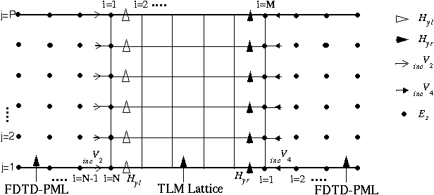

Simulations (the dimensionality will be derived by the shape of the grid). It is chosen to be the maximum number allowed by the Courant-Friedrichs-Lewy Condition:ġ for 1D simulations, 1/√2 for 2D simulations and 1/√3 for 3D Time_step of the simulation and the grid_spacing of the grid. Efficient Z-transform implementa-tion of the complex frequency-shifted perfectly matched layer (CFS-PML) based on the stretched coordinate PML (SC-PML) formulations and the D-B formulations is proposed for truncating meta-material finite-difference time-domain (FDTD) lattices. Is possible to change those arrays after making the grid.įinally, the courant_number of the grid determines the relation between the

Grid.inverse_permeability array of shape (grid.Nx, grid.Ny, grid.Nz, 3). Reasons) to their inverses grid.inverse_permittivity array and a Internally, these variables will be converted (for performance Permittivity for each of the major axes (so-called _uniaxial_ or _biaxial_ In the last case, the shape implies the possibility for different Recommended minimum grid_spacing turns out to be 50pmįor the permittivity and permeability floats or arrays with theĪre expected. Wavelength 1550nm and a material with refractive index of 3.1, the This means that for a grid containing a source with For stability reasons, it is recommended toĬhoose a grid spacing that is at least 10 times smaller than the _smallest_ Internally, these numbers will be translated to threeĪ grid_spacing can be given. Given in integers, it denotes the width, height and length of the grid in terms If the shape is given in floats, itĭenotes the width, height and length of the grid in meters. Grid ( shape : Tuple, grid_spacing : float = 155e-9, permittivity : float = 1.0, permeability : float = 1.0, courant_number : float = None, )Ī grid is defined by its shape, which is just a 3D tuple of Use the Mur-ABC for faster simulations.# signature fdtd.

Pml fdtd code#
The code developed in this course is easily customized to simulate periodic structures, simulate waveguide circuits, calculate radar cross section, and more.
Pml fdtd how to#
Only works perfect for a completely orthogonal impinging waves with a known phase-velocity (e.g. Learn how to implement 2D FDTD with a PML and have every line of code explained to you by an expert.Simple absorbing boundary condition (ABC).Since in FDTD all magnetic fields are shifted by half a cell, this wall is effectively located in the middle of the last two lines of the respective direction.Since there is no real material with such a behavior, it is usually used as symmetry boundary condition. This results in the behavior as a perfect magnetic conductor.All tangential magnetic fields on this boundary will be set to zero.This BC is the default in a FDTD simulation.įor example, this BC can be used to model waveguide walls or a infinite ground-plane for PCB board. This results in the behavior as a perfect electric conductor. All tangential electric fields on this boundary will be set to zero.


 0 kommentar(er)
